
WATER & COOLING
Clean water.
Cool compute.
Two platforms. One closed loop.
Water treatment and waste-heat cooling built to run as one system: contaminants destroyed, heat reused, water recovered instead of discharged.
CONTACT THE GAIA TEAMWhat industry uses, industry can clean
- 4.4%Of all U.S. electricity was consumed by data centers in 2023, projected to reach 6.7% to 12% by 2028.Source: Lawrence Berkeley National Laboratory and U.S. Department of Energy, 2024
- 45%Of U.S. tap water is estimated to contain at least one type of PFAS.Source: U.S. Geological Survey, 2023
- 115xMore granular activated carbon can be required to remove the same PFAS when source water carries high organic carbon.Source: Marmon Water, UCONN Water Conference 2023
- $50BEstimated cost for U.S. drinking water utilities to clean up PFAS over the next 20 years.Source: Robeco and National League of Cities, 2025
THE PROBLEM
A fifty billion dollar problem.
On a 2031 clock.
Water utilities have to remove chemicals they never produced, on a deadline set for them, using the most expensive version of the technology available.
PFAS removal is now a mandatory capital program for every public water system in the country, and the price of compliance rises with whatever else is in the water.
That price is the opportunity: the utilities, the sites, and the industries that must treat water are already funded and already on the clock.
- $50 billion is the estimated cost for drinking water utilities alone to clean up PFAS over the next 20 years, with an additional $2.5B to $3.2B per year in compliance costs once treatment, monitoring, and public reporting are included.Robeco and National League of Cities; Black & Veatch, 2025
- $31 billion is the estimated federal obligation to clean up contamination at installations, where PFOS and PFOA were found above 70 parts per trillion at 55 locations, more than 94% above the current 4 ppt limit for PFOA and PFOS.U.S. Department of Defense and U.S. Government Accountability Office, 2021
- The deadline moved, the limits did not. The U.S. Environmental Protection Agency set enforceable limits of 4 parts per trillion for PFOA and PFOS in 2024 and proposed extending the compliance date from 2029 to 2031. The standard stands.U.S. Environmental Protection Agency, 2024 and 2025
- 41,828 industrial and municipal sites are known to produce or use PFAS, or are suspected of it.Environmental Working Group, 2021
- Globally, 2.1 billion people still lack safely managed drinking water.WHO and UNICEF Joint Monitoring Programme, 2025
THE GAC BOTTLENECK
The Achilles heel
is total organic carbon.
Granular activated carbon is the default answer for PFAS. What it costs is set by everything else the carbon has to absorb first.
Carbon beds don't die of PFAS. They die of the organic carbon that exhausts them first, and organic carbon varies by more than an order of magnitude between water sources.
Remove the organic carbon upstream and the same bed treats far more water, which is where the money is. Florida pays roughly 100 times more per facility than North Carolina for the same outcome.
| Groundwater source | Total organic carbon | GAC use rate per 1,000 gallons | Annual GAC cost |
|---|---|---|---|
| North Carolina | Under 0.3 mg/L | 0.05 lb | $14,235 |
| Colorado | 1.3 mg/L | 0.71 lb | $190,530 |
| Florida | 4.6 mg/L | 5.75 lb | $1,554,170 |
Carbon priced at $0.95 per pound at commercial scale. Source: Marmon Water, UCONN Water Conference 2023; U.S. Environmental Protection Agency; Florida Department of Environmental Protection.
- Florida: $6.37 billion versus $58 million. Across the state's regulated wastewater facilities, removing total organic carbon first would cut materials cost for PFAS removal by more than 99%.Marmon Water; Florida Department of Environmental Protection, 2025
- More than 4,100 active wastewater treatment facilities are regulated in Florida alone, roughly 2,000 domestic and 2,100 industrial, which is why one state's carbon bill reaches into the billions.Florida Department of Environmental Protection, 2025
- Nitrate makes it worse. Of four common inorganic anions tested, nitrate had the most pronounced negative effect on the adsorption of short-chain PFAS, so agricultural runoff and recirculating aquaculture effluent raise the cost of every gallon treated.Journal of Water Process Engineering
HYDRODYNAMIC CAVITATION
Destroy the carbon.
Protect the carbon bed.
Gaia's water platform treats the organic carbon problem ahead of the carbon bed, so the material that removes PFAS lasts the way it was specified to last.
Hydrodynamic cavitation concentrates energy into collapse events violent enough to break down organic carbon in water, with no moving parts and nothing to replace in the treatment path.
Fewer carbon changes per year means less material, less transport, less regeneration, and less disposal at every facility that has to meet the standard by 2031.
P1 5.9 barbefore the pinch
P2 0.02 barat the throat
P3 1.4 barafter the throat
Three gauges share one 0–6 bar scale: the throat reads the vapour pressure of water, so the cavities cannot stay liquid — they open.
- 6,000 K micro-jets. Collapsing cavitation bubbles release shock waves and high-speed micro-jets that raise the surrounding water above 6,000 K, roughly 10,340 degrees Fahrenheit, at the surface temperature of the sun.Voltek Water; Ultrasonics Sonochemistry
- 85% total organic carbon removed in one hour. Published hydrodynamic cavitation studies report 85% TOC removal within a single hour of treatment time, with successful mineralization.Ultrasonics Sonochemistry; Bioresources and Bioprocessing
- No consumables in the treatment path. The process uses high-pressure water and a designed expansion chamber rather than membranes, chemicals, or media that must be replaced.Gaia water platform technical review, 2025
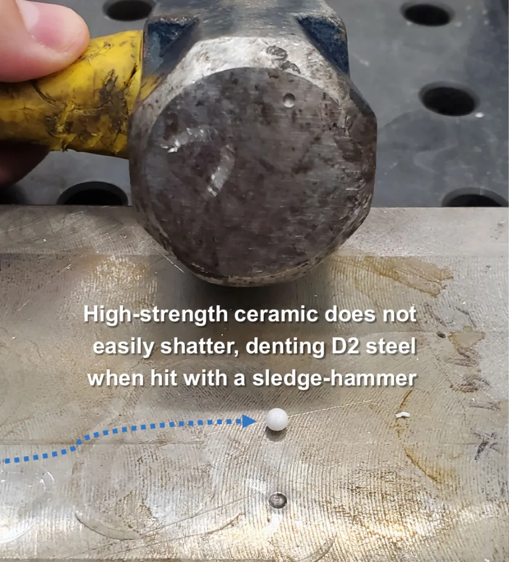
- Shatter-resistant technical ceramic. Orifice plates are being developed in a technical ceramic that is near the hardness of diamond, resists the erosion that destroys conventional metals, and is inherently self-cleaning.Gaia water platform technical review, 2025
- One architecture, many scales. The same platform is designed to serve whole-home and pool systems through municipal and industrial treatment volumes.Gaia water platform technical review, 2025
WHY THE MATERIAL MATTERS
Cavitation destroys ordinary metals. Micro-jets that reach 6,000 K will eat through the parts that create them, which is why the durable answer is a ceramic that refuses to shatter and refuses to erode.
Gaia's cavitation unit is in development. Performance figures above are from published hydrodynamic cavitation studies, not from a commercial installation.
CHLORINE CONTROL
Corrosion,
designed out.
Chlorine keeps pools safe and quietly destroys everything in the room around them. Ten parts per billion is enough.
The chlorine control platform removes chlorine from the air and the water it off-gasses into, which stops a replacement cycle that facilities pay for over and over.
Registers, cameras, laptops, fire panels, conduit, and shelving are the recurring cost of chlorine corrosion. Removing the cause is cheaper than replacing the effects.
- More than 99% reduction in measured store chlorine levels, with corrosion issues eliminated, verified in three or more in-store trials.Gaia water platform technical review, 2025
- 10 parts per billion is corrosive to copper and silver, the metals in point-of-sale registers, security cameras, laptops, fire sprinkler systems, and electrical conduit.Gaia water platform technical review, 2025
- 5,000 pool supply stores and more than 60,000 hospitality locations with indoor pools in the United States are the addressable footprint, served today through national pool-industry distribution partners.Gaia water platform technical review, 2025
ADDRESSABLE MARKETS
Six markets.
One platform.
The same cavitation platform addresses treatable water everywhere it is regulated, consumed, or discharged.
Pools
10.4 million residential pools and 309,000 public or commercial pools, about 55,000 of them at hotels and resorts.
$19.4B U.S. pool equipment and maintenance market in 2023, projected to reach $42.2B by 2030.
Municipal water
152,000 public drinking water systems across the United States.
$50B in cleanup over 20 years and $2.5B to $3.2B per year in ongoing compliance costs.
Well water and whole home
23 million U.S. households rely on private wells for drinking water.
$6.8B U.S. water purifier market in 2024, projected to reach $10.6B by 2032.
Federal installations
4,790 sites worldwide covering more than 27 million acres.
$31B estimated federal PFAS cleanup obligation, and no installation has begun long-term cleanup today.
Indoor agriculture
More than 112 million square feet of U.S. greenhouse vegetable production.
$387M U.S. greenhouse irrigation systems market in 2022.
Aquaculture
3,453 aquaculture farms in the United States.
$20.3B deficit between U.S. seafood imports and exports.
HOW THE PLATFORM EARNS
Units through distribution. Cavitation units sold through water-industry partners into their existing industrial, municipal, pool and spa, consumer, food and beverage, agriculture, and aquaculture customers.
Treatment as a service per gallon. A per-gallon fee to remove total organic carbon, priced against the carbon savings the customer stops paying for: raw material, pre-filtering, transport, and regeneration or disposal.
BRINE & RESOURCE RECOVERY
Brine as a feedstock,
not a disposal line.
The same membrane and crystallization loop that cools the campus concentrates brine, and concentrated brine is where the valuable minerals are.
Treatment normally ends in a waste stream. This platform is designed to end in products, with far less water leaving the site and far less brine needing disposal.
Recovered minerals and recovered process materials are designed to change the cost model of treatment itself, and every gallon kept in the loop is a gallon not purchased or discharged.
Designed capabilities, in development
- Mineral recovery from brine. Recovery of valuable minerals including lithium, iodine, and bromine from brines and contaminated sources.Gaia water platform technical review, 2025
- More usable water per unit of feed. Maximizing recoverable water to reduce consumption and support future injection requirements.Gaia water platform technical review, 2025
- Less retentate, less discharge. Lower water consumption through minimal reverse-osmosis retentate discharge, and a reduced volume of brine requiring discharge or disposal.Gaia water platform technical review, 2025
- High-value process materials recovered, not disposed. Recovering materials that would otherwise be written off as waste.Gaia water platform technical review, 2025
WASTE-HEAT COOLING
The heat is already there.
Put it to work.
A closed-loop cooling platform that uses the waste heat from computing as its energy input, instead of paying to reject it.
Every joule pumped through a processor leaves as heat. Gaia's cooling platform captures that heat at 60 to 70 degrees Celsius and turns it into cold fluid, producing ultrapure distillate as a byproduct.
Cooling is the second-largest power draw in most facilities and the first thing constrained by water. A platform that runs on waste heat addresses both at once, with no evaporative water demand in the loop.
- 01Capture. Direct-to-chip liquid cooling collects 65% to 75% of server heat as liquid returning at 60 to 70 degrees Celsius.
- 02Separate. A specialized membrane distills the coolant from the water it is carried in, operating most efficiently at waste heat of 60 degrees Celsius or warmer.
- 03Recrystallize. The concentrated coolant recrystallizes in an endothermic reaction, then remixes with the separated water to deliver cooling on demand.
- 04Deliver and reject. A return cold loop of 15 degrees Celsius or cooler serves building air conditioning and direct-to-chip cooling, while dry coolers reject the remaining heat to ambient air.
Projected: 60°C - 70°C at the chips, 30°C - 40°C distilled to ultrapure water, 15°C back out to the cold loop, 20°C - 25°C returned to the chips. Point at a machine to read its part of the loop.
The loop
- 1Direct-to-Chip (D2C) cold plates60°C - 70°C (D2C)
- 2Membrane feed · Membrane distillate60°C - 70°C in · 30°C - 40°C out
- 3Distillate Tank (ultrapure water)30°C - 40°C
- 4Recrystallizer & Endothermic Tank (series of units)60°C - 70°C in · 15°C out
- 5Server Room A/C15°C in · 20°C - 25°C (A/C) return
- 6Dry Cooler (ambient chiller)Q out to ambient air · no evaporative water
The heat
- Q inHeat into the loopThe processors at the cold plates, and the room at the A/C.
- Q outHeat to ambient airThe dry cooler rejects what the loop cannot use, without evaporating water.
The lines
- Membrane feedHot · leaving the cold plates
- Concentrated coolantHot · concentrate on to the recrystallizer
- Membrane distillate (ultrapure water)Water · distillate to the tank
- Q outWarm · the last heat, to ambient air
- 15°CCold · cold fluid to the air conditioner
- 20°C - 25°C (A/C)Cool · the return closes the loop
The temperatures in the loop are projected from the platform's model, not measured.
Projected performance, modeled
- Projected coefficient of performance of 11.5. For a 10,000 square foot, 300-ton facility, against 5.2 for a centrifugal chiller, based on 64.5 kilowatts of pumps and dry-cooler fans.Projected, theoretical model
- Projected cooling cost of about $106,000 per year, against $235,000 for a centrifugal chiller and $488,000 for direct-expansion computer room air conditioning at the same load: about 78% savings against the conventional baseline.Projected, theoretical model
- Projected cooling power usage effectiveness of 0.09, against an industry average of 1.56 across all facility types.Projected, theoretical model; Uptime Institute Global Data Center Survey, 2024
- Honest limits. The model covers the coolant loop only: three pumps at 21.5 kilowatts and 27 kilowatts of dry-cooler fans. It excludes direct-to-chip pumping and server air conditioning fan power. System cost is still to be determined, and actual performance will depend on building design, seasonal temperatures, and real-time loads.Gaia cooling platform technical review, 2025
BEYOND THE DATA CENTER
The same closed-loop chemistry is designed to extend to commercial refrigeration, building air conditioning, and the cold chain, including packaging and material handling where a solidified coolant has to hold temperature through a shipment.
The coolant is designed to be non-toxic, reusable, and fully compostable, with an operating range from 42 degrees Fahrenheit down to 20 degrees below zero in its solidified form. Cold-chain and packaging applications remain in development.
THE COOLING MARKET
Cooling equipment is the market this platform sells into: $82.3 billion in 2021, $146.8 billion projected for 2025.
| Cooling segment | 2021 estimate | 2025 projection | Five-year growth |
|---|---|---|---|
| Cooling towers | $2.9B | $4.8B | +$1.9B |
| Evaporative coolers | $5.8B | $17.0B | +$11.2B |
| Data center cooling | $8.6B | $20.7B | +$12.1B |
| Industrial chillers | $9.6B | $11.2B | +$1.6B |
| District cooling * | $21.9B | $39.9B | +$18.0B |
| Commercial refrigeration * | $33.5B | $53.2B | +$19.7B |
| Totals | $82.3B | $146.8B | +$64.5B |
A current read on the same segment. Independent market research valued the global data center cooling market at $18.78 billion in 2025, and projects $54.18 billion by 2034, a 12.6% compound annual growth rate. That 2025 estimate lands within about 10 percent of the $20.7 billion projected for the same year in the 2021 analysis above.
Third-party reports compiled for the 2021 estimates: Million Insights, MarketsandMarkets, Grand View Research, Market Insight Reports, and Fortune Business Insights. Current estimate: Fortune Business Insights, Data Center Cooling Market, updated June 2026.
*District cooling and commercial refrigeration need membranes now in development with the University of Wyoming and the University of Connecticut: membranes that do not need waste heat.
WASTE HEAT IS EVERYWHERE
The membrane approach runs best at 60 degrees Celsius or above, a level most of these sources reach, so the same loop can serve industries well beyond data centers.
| Source | Typical temperature |
|---|---|
| Generic unit or process | |
| Boiler flue gases | 110–260 °C |
| Waste heat from air-compressor cooling | 30–60 °C |
| Condensate from steam heating and spent cooling water | 60–90 °C |
| Industrial sector — representative rows | |
| Petrochemical: stack gas from vacuum distillation | 216 °C |
| Iron and steel making: blast stove exhaust | 250 °C |
| Cement: kiln exhaust with 5- or 6-stage preheaters | 204–300 °C |
| Food and drink: extracted air from fryers or ovens | 150–200 °C |
| Textile: stenter exhaust from fabric drying and finishing | 180 °C |
40%
THE COOLING BILL
Cooling can account for up to 40 percent of a data center’s energy use, according to the U.S. Department of Energy. That is in line with the 2021 analysis behind this page, where most facilities spend over 32 percent of their power on cooling, which is the load a waste-heat platform is designed to displace.
Source: U.S. Department of Energy, May 2023.
INSIDE THE GAIA CAMPUS
Waste heat in.
Clean water out.
The two platforms are designed to feed each other on the campus, which is the point of building them together.
Compute produces heat
Direct-to-chip cooling captures server heat as liquid at 60 to 70 degrees Celsius.
Heat produces cold
Membrane distillation and endothermic recrystallization convert waste heat into a 15 degree Celsius cold loop.
Cooling produces water
The membrane loop yields ultrapure distillate that returns to the campus water platform instead of evaporating away.
Treatment returns water to use
Contaminants and organic carbon are destroyed upstream, so recovered water is available for reuse across operations.
On the campus, the water platform treats what the campus and its industrial tenants produce, and the cooling platform turns the heat those operations generate into the cooling they need.
Shared infrastructure is designed to add capacity without adding pressure on local utilities, with surplus capacity intended to support surrounding communities where feasible and permitted.
Explore the Gaia ecosystem, Gaia OS, and the campus model. The human-facing front door to all of it is Gaia Discovery Park.
LET’S BUILD WHAT’S NEXT
Two platforms.
One conversation.
Utilities, pool operators, data center developers, industrial water users, and co-investors can reach the Gaia team directly. Pilots and distribution partnerships are open now.
CONTACT THE GAIA TEAM- Partner
- Pilot
- Co-invest
- Deploy